
Thermal Power Plant Process Flow Diagram

Sankey Diagrams
The energy and exergy flow diagram of the HP is illustrated in Fig. 11 where the heat flow ... wells are drilled in total. For point A, processing plant 1 and processing plant 3 are constructed with capacity of million standard cubic feet (MMscf) of shale gas per year and MMscf of shale gas per year, respectively. For point B, processing plant 1 is constructed with a capacity of ...

Process flow diagram
· One of the initial steps to creating a process flow diagram is to add all of the equipment that is in the plant. Not only is the major equipment, such as distillation columns, reactors, and tanks, necessary to be shown in a PFD, so is the equipment such as the heat exchangers, the pumps, reactors, mixers, etc). The following figures will display the most common symbols found in process flow ...

Desalination In Saudi Arabia An Overview
FLOW DIAGRAM FOR DUAL PURPOSE PLANT WITH THERMAL DESALINATION PLANT Anti foam SWP P Cl 2 CW D/A B H. Rej BP Turbine G H. Recovery ESP FGD Fuel Gases (NO x, SO x, P, CO 2) Fuel HFO TBT = 85c – 112c B H Vent Reject to sea BRPP BDPP antifoam antiscalant PW
Cogeneration Steam Power Plant (11/8/09)
Problem A Cogeneration Steam Power Plant. Cogeneration or Combined Heat and Power (CHP) is the utilization of 2 forms of energy from 1 source : hot water/heat and electricity from one genset.. According to the American Council for an Energy Efficient Economy (), the world's first commercial power plant Thomas Edison's Pearl Street Station built in 1882 was a cogeneration plant ...
PFD
FREE online Process Flow Diagram drawing template enabled for the FREE online Google Docs.. Make your own Process Flow diagrams with this FREE online drawing tool. Log in to your Google Account (Google Accounts are free) and copy ("File > Make a copy") this online Process Flow Drawing template to start making your own drawings.. Select, copy and paste the components you want to use.

Engineering Design Elements of a TwoPhase Thermosyphon to ...
Several options are being considered to transfer multimegawatt thermal power over such a distance. One option is simply to produce only electricity, transfer it by wire to the hydrogen plant, and then reconvert the electric energy to heat via Joule or induction heating. Electrical transport, however, suffers energy losses of 60–70% because of the thermaltoelectric conversion inherent in ...


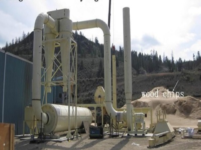
Biomass power plant process flow diagram
Biomass power plant process flow diagram School of Engineering, Faculty of Science, Engineering and Built Environment, Deakin University, Victoria 3220, Australia School of Engineering and Technology, Gladstone Engineering Centre, Higher Eduion Division, Central Queensland University, Gladstone, Queensland 4680, Australia School of Engineering and
What is Boiler and Condenser Pressure
· The process of superheating of water vapor in the Ts diagram is provided in the figure between state E and saturation vapor curve. As can be seen also wet steam turbines ( used in nuclear power plants) use superheated steam especially at the inlet of lowpressure stages.
Thermodynamic Analysis of Geothermal Power Generation ...
geothermal power plants in detail. With such a mathematic model, both the capacity and efficiency of the power plants are calculated. The results are given in a diagram which displays the optimum flash temperature for combined power generation system and the optimum design parameters determined by the temperature. The calculated result shows that when the average temperature of cooling water ...
What is Combined Cycle Power Plant?
Nuclear Power Plant – Working Principle, Advantages, Disadvantages with Diagram; Working of Combined Cycle Power Plant. Now, we would focus on the most important part of this article which is nothing but the working of the combined cycle power plant. See the below points to .
Geothermal Energy
Geothermal Power plant Diagram : ... The corrosive and abrasive geothermal fluid reduces the life of plants. Thermal energy cannot be distributed easily over a long distance ( longer than 30 km ) Initial capital and installation costs are high. Appliions of Geothermal Energy : It is used in generating electric power. It is used in industrial process heat. It is used in space heating for ...

Rankine Cycle
Rankine cycle process Ts diagram . In case of the process 1 2 – Isentropic compression. In this process, the working fluid will be pumped from low pressure to high pressure. The fluid is in the liquid form at the start of this process. The water is heated to the saturation temperature, keeping the entropy constant. Process 23 – Constant Pressure Heat Addition Process in Boiler. In case ...

What is a Process Flow Diagram | Lucidchart
A Process Flow Diagram (PFD) is a type of flowchart that illustrates the relationships between major components at an industrial plant. It's most often used in chemical engineering and process engineering, though its concepts are sometimes applied to other processes as well. It's used to document a process, improve a process or model a new one. Depending on its use and content, it may also ...

Coal Power Plant Process Flow Diagram
Block diagram of coal mill model These have impacted the coal mill and power plant oper ation Process Flow Diagram for Power generation from Pulverised . Thermal power station Wikipedia A thermal power station is a power station in which heat energy is converted to electric power. Get Price . Energy and Exergy Analysis of Coal Fired Power Plant. Energy and Exergy Analysis of Coal Fired Power ...


Condenser in Thermal Power Plants | Power4you
· Thermal Power Plant is based on the Rankine cycle and in Ideal Rankine cycle, there are 4 processes and those are Heat Addition at Constant Pressure in Boiler, Isentropic Expansion in Turbine, Constant Pressure Heat Rejection in Condenser and Isentropic Compression in now we will discuss about the condenser, which plays a very vital role in the cycle.

coal fired power plant process flow diagram
Coal Fired Power Station Flow Diagram Diagram. Dec 10, 2012 · Simplified Process Flow Diagram Of The Coal Fired Power Plant See. Coal fired boiler diagram power plant coal fired thermal power plants supercritical co2 brayton cycles for coal fired power plants from coal to electricity ca mining recruitment jobs. Trending Posts.

kolkata power plant flow control diagrams
Process Flow Diagram A Process Flow Diagram (PFD) is a diagram which shows the relationships between the main components in a system. Process Flow Diagrams are widely used by engineers in chemical and process engineering, they allows to indie the general flow of plant process streams and equipment, helps to design the petroleum refineries ... More. Power Plant Diagram Examples .