
Diagram Of Coal Mill In Power Plant


Flexibilization of coalfired power plants by Dynamic ...
Flexibilization of coalfired power plants by Dynamic Simulation Marcel Richter1 Florian Möllenbruck1 Andreas Starinski1 Gerd Oeljeklaus1 Klaus Görner1 1Chair of Environmental Process Engineering and Plant Design, University of DuisburgEssen, Germany {, } Abstract Due to the strong expansion of renewable energies, the
IGCC Process System Sections |
Simplified Flow Diagram of a Typical Combined Cycle Plant. Gas Turbine Clean syngas is burned with compressed air and diluents in the gas turbine to generate power. Modern GTs have been modified from conventional NG turbines, and commercially demonstrated to be able to burn low and medium BTU syngas from coal gasifiion.

Energy system components system decomposition
Most conventional energy systems will use a nonrenewable input, such as coal, gas, or oil products. Due to economiesofscale, these have developed into systems that may run at a very large capacity – a 1,000 MW power plant is no exception; nor is a refinery that converts several 100,000s of barrels of crude oil a day the analysis, we may observe that such systems translate to large ...
THERMAL POWER PLANTS
2. Process description of a coalfired power plant A coalfired power plant burns coal to produce electricity. In a typical coalfired plant, there are pulverisers to mill the coal to a fine powder for burning in a combustion chamber of the boiler. The heat produced from the burning of the coal generates steam at high temperature and pressure.
Schematic Diagram of Thermal Power Station | Thermal power ...
A coal based thermal power plant converts the chemical energy of the coal into electrical energy. This is achieved by raising the steam in the CFB boilers, expanding it through the turbine and coupling the turbines to the generators which converts mechanical energy into electrical energy.


schematic diagram of coal mill
schematic diagram of coal mill. schematic pulveriser for coal pdfcrusherasia schematic pulveriser for coal pdf control for a power plant coal pulverizer diagram in mak Read more pulverise coal steam turbine apcivilsupplicoin schematic pulveriser for coal pdf Of coal burners loed at different elevation at The schematic diagram of a turbine is shown in figure


Monitoring Model of Coal Mill in Power Plant Based on Big ...
· Abstract: In order to monitor the wear condition of grinding roller of coal mill in power plant and improve the reliability of production equipment, it is necessary to establish a state monitoring model with high accuracy and good prediction effect. It has been shown that the power of coal mill can reflect the wear degree of grinding roller.

Coal Power Plant Diagram
· 41+ Coal Power Plant Diagram coal used in indian power stations has large amounts of ash (about 50%) which contain abrasive mineral species such as hard quartz (up to 15 hot corrosion and erosion are recognized as serious problems in coal based power generation plants .

Flow Diagram of a Steam Thermal Power Plant | Electrical4U
· Flow Diagram of a Steam Thermal Power Plant. March 7, 2021. February 24, 2012. by Electrical4U. A thermal power generating plant works based on the Rankine Cycle. There are mainly three primary inputs given to thermal power generating plants for producing electricity. These three most essential elements are coal, air, and water.

Final Thermal Power Plant Cover
Section Formula for target setting for Coal based Thermal Power Plant 5 (a) Design Net Heat Rate 5 (b) Operating Net Heat Rate 5 ... General details required in wood based Pulp and Paper Mills 187 Table 26: Documents required wood based Pulp and Paper Mills 191 ... ExCCGT Energy balance diagram 157 Figure 11: Product Mix diagram 159


UNIT1 THERMAL POWER STATIONS Introduction
THERMAL POWER STATIONS Introduction Thermal energy is the major source of power generation in India. More than 60% of electric power is produced by steam plants in India. India has large deposit of coal (about 170 billion tonnes), 5th largest in world. Indian coals are classified as AG grade coals.

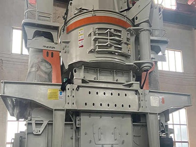
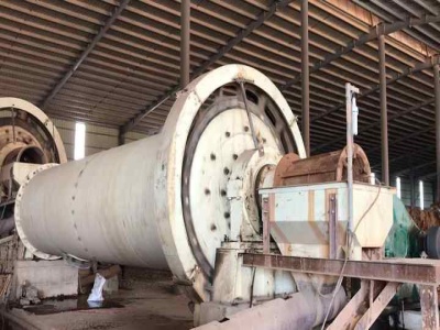
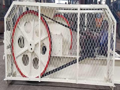
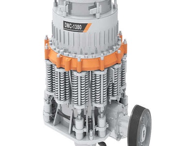
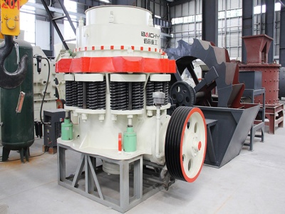
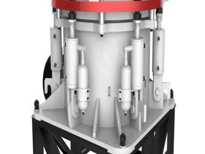
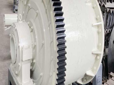
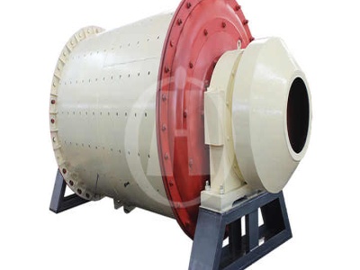
Coal Mill
Coal Mill. Coal mills grind the coal into fine powder, and the primary air entering the mill dries and drives the coal into the power plant furnace for combustion. From: Journal of Process Control, 2015. Related terms: Silos; Biomass; Kilns; Steam Generator; Cement Plant; Grindability; Preheater
Coal fired power plant
Coal fired power plants also known as coal fired power stations are facilities that burn coal to make steam in order to generate stations, seen in Figure 1, provide ~40% of the world's electricity. Countries such as South Africa use coal for 94% of their electricity and China and India use coal for 7075% of their electricity needs, however the amount of coal China uses ...
Implementation Of Quality Management System For Coal ...
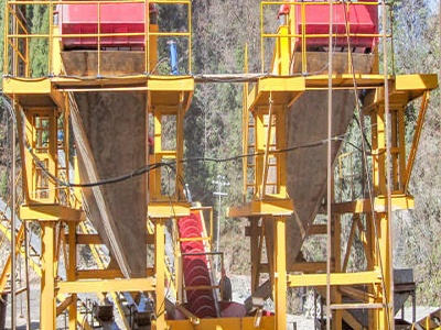
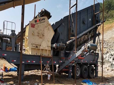
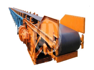
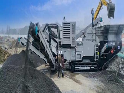
In the thermal power plants maximum requirements of fuel is a coal. Coal handling plant ... The basic layout of Coal Handling Plant is shown by block diagram. (See Fig. No5) the coal is unloaded at various unloading station and transported by conveyors to crushing ... bunker the coal flows through coal mills to .
Boiler Control for FossilFired Utility Boilers
Total coal flow is calculated by summing the coal flow for each mill. The type of coal flow measurement varies from plant to plant, and may be derived from feeder speed, mill differential, feeder demand, etc. A mill model is included to more accurately convert the coal flow measurement into a representation of the energy release in the furnace.
Line Diagram Of Coal Mill
Coal mill pulverizer in thermal power plants Nov 17, 2012 The dashed line estimates the increase in mill capacity in going from a highvolatile B bituminous coal with a 55 HGI, 12% moisture and a desired mill output of 70% through a 200 mesh screen to a highvolatile B bituminous coal with an HGI value .


Monitoring Model of Coal Mill in Power Plant Based on Big ...
· In order to monitor the wear condition of grinding roller of coal mill in power plant and improve the reliability of production equipment, it is necessary to establish a state monitoring model with high accuracy and good prediction effect. It has been shown that the power of coal mill can reflect the wear degree of grinding roller. If the voltage and power factor of coal mill are constant ...
Optimization of Operation and Maintenance in Thermal Power ...
Overview of Kansai Electric Power 3 Established in 1951 Electricity Sales : 127,516 GW Tokyo Installed Plant Capacity : 46 GW Kansai Region 52% 21% 19% 8% Fossil Nuclear Hydro Renewable energy etc. Capacity (2016) 10% 61% 29% Coal LNG Oil Fossil Fuel .
Pulverised Coal Combustion
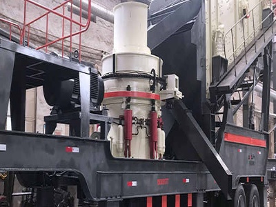
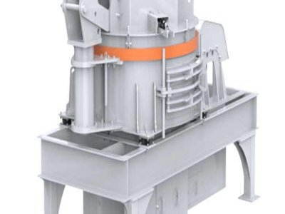
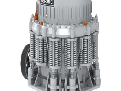
Pulverized coal (PC) combustion is presently the system of choice for coalfired powergenerating plants. In PC combustion, the coal is dried and is ground to a specified fineness, with a maximum particle size of 250–300 μm, depending on the reactivity of the coal.


Status of ClaRaCCS: Modelling and Simulation of CoalFired ...
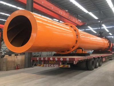
Stateoftheart conventional hardcoalfired power plants burn pulverised coal in the steam generator with air. The heat is transferred to a steam cycle that converts it to electric energy. The general simplified process scheme of the power plant is shown in figure 1. Mills pulverise and dry the raw hardcoal. The raw

Strategic Report The New Role of CoalFired Power Plant in ...
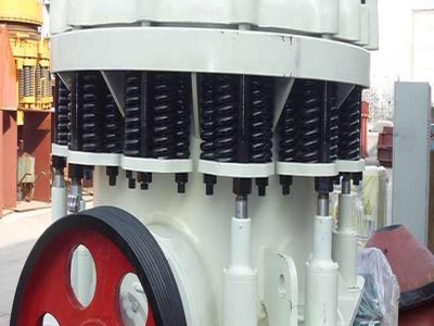
Overview of Vertical Mill and Ball Mill ..... 33 Figure 20. A Case Example of Steam Temperature Control Improvement ... Schematic Diagram of AQCS by Type ... Strategic Report on the New Role of Coalfired Power Plant in the Era of Energy Transition