
Diagram Labelled Equipment

Weather Instruments: The 25 Most Used Devices | NWC
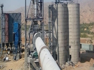
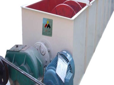
May 07, 2015 · Pan evaporation. Pan evaporation instrument is used to measure the effective evaporation. Several types are used; however, one of the most used is the "Class A". This is a cylindrical galvanized steel tank, m in diameter and 25 cm deep. It .
![Parts of a Draft Beer System How They Work [Diagram]](/grz2kxi/1148.jpg)
![Parts of a Draft Beer System How They Work [Diagram]](/grz2kxi/551.jpg)
Parts of a Draft Beer System How They Work [Diagram]
Glycol Cooled Draft System. If the kegs cannot be kept refrigerated within close proximity to the draft tower and faucets, then a long draw draft system is required. A glycol cooled draft system is a long draw system that uses a glycol chiller or power pack to pump a mixture of glycol and water through a trunk line that keeps draft beer at a consistent temperature as it travels from keg to tap.

How to Draw a Science Diagram | EdrawMax Online
More Free Science Diagram Templates/Examples. In addition to picking from the EdrawMax Online portal itself, you can also download many other science diagram templates that the developer has made available for you. A few popular ones include: Cell Diagram – This template has a prebuilt labeled diagram of a cell.
Circuit Diagram And Its Components
Circuit diagrams are used for the design, construction and maintenance of electrical and electronic equipment. What is a Circuit Diagram? A circuit diagram is a simplified representation of the components of an electrical circuit using either the images of the distinct parts or standard symbols. It shows the relative positions of all the ...
Manuals
Rotary Cutters. Single Spindle. 100 Series 200 Series 400 Series GR Series Twister 10 Series Twister 20 Series Twister 30 Series. MultiSpindle. SE Series TW Series Turbo Series. FlexWing. TS10 TS12 Stealth 2150 15′ FlexWing 3000 Series 4000 Series 5000 Series 6000 Series 7026 26′ FlexWing.
Laboratory Equipment and Scientific Diagrams – Worksheet ...
Learning Outcomes. By the end of this worksheet students will be able to: Identify common pieces of scientific laboratory equipment. Draw scientific diagrams of common pieces of scientific laboratory equipment. Draw labelled scientific diagrams of simple experimental setups. This resource is also included in the Year 7 Chemistry PDF Workbook.


Network design – Different ways of connecting to the ...
Nov 28, 2016 · How to connect to the Internet using different network solutions. This document provides information in the form of Network diagrams on how to obtain connection to the Internet using different product egories advise is given on the way IP address schemes should be used formally (indipendently from the IP numbers actually used).


Rack Diagram
This makes building a rack diagram much faster and more accurate than trying to draw one by hand. Create the rack. Draw the racks on the page first. They should be drawn to scale exactly and should show every feature of the actual rack in real life. Arrange equipment. Draw each piece of equipment to scale. Placing a label inside the area of ...
Get It Done: Use Visio to diagram your rack server equipment
Mar 15, 2002 · Your equipment manufacturer may provide tools to help you diagram your rack equipment—good news for those of you with deep brand loyalty. Some of .
Drawing FreeBody Diagrams
Drawing FreeBody Diagrams. Freebody diagrams are diagrams used to show the relative magnitude and direction of all forces acting upon an object in a given situation. A freebody diagram is a special example of the vector diagrams that were discussed in an earlier unit. These diagrams will be used throughout our study of physics.

Diagram Examples Drawn Using Creately | Creately
Learn How UML Diagrams works. UML diagrams are great for designing and documenting systems. UML Smart objects with power features help you draw faster and support 14 types of UML diagrams. Many UML diagram examples to get started. Connect multiple diagrams with inline links. Complete library with Smart UML modeling objects.

Network Diagram Guide: Learn How to Draw Network Diagrams ...
Sep 13, 2021 · Once you select a diagram template; Add relevant equipment (by inserting symbols): As shown above, Creately loads the relevant shapes, tools, arrows etc. You can begin by inserting computers, servers, routers, firewalls etc on the page. Label the symbols/devices: Add components names for clarity for anyone who wants to refer it. If you do not ...


Engineering Standards Manual: Standard Drawings Details
Sep 30, 2004 · LANL Standard Drawings and Details either (1) depict required format/content or (2) are templates that are completed by a Design Agency (LANL or external AE) for a design drawing package, in a manner similar to specifiions.
Kawasaki FR691VBS10 4 Stroke Engine FR691V Parts Diagrams
Kawasaki FR691VBS10 4 Stroke Engine FR691V Exploded View parts lookup by model. Complete exploded views of all the major manufacturers. It is EASY and FREE

How to Read a PID? (Piping Instrumentation Diagram ...
Jan 27, 2020 · The symbols contained in PIDs represent the equipment in the process such as actuators, sensors, and controllers. Process equipment such as valves, instruments, and pipelines are identified by codes and symbols. As well as devices and pipelines, a PID will commonly contain information on vents, drains, and sampling lines as well as flow ...


Vernier Calliper Diagram, Working principle
Dec 09, 2017 · Vernier Calliper Diagram. Vernier Calliper working principle: Vernier scale is a visual aid, That allows the user to read measurements more precisely than any other instrument. Vernier scale indies where the measurement lies in between two of the graduations on the main scale.

Piping and Instrumentation Diagram (PID) | Diagrams ...
Jul 03, 2012 · Each PFD will require many PIDs to provide the necessary data. Figure is a representative PID for the distillation section of the benzene process shown in Figure PID presented in Figure provides information on the piping, and this is included as part of the diagram. As an alternative, each pipe can be numbered, and the specifics of every line can be provided in a .
Drawing Equipment |
Jan 01, 2018 · This piece of equipment is not only used in graphics for constructing accurate drawings but is also used in subjects like Mathematics. Also available for graphics is a full circle protractor which can be used to accurately measure angles greater than 180 degrees. Diagram 1 – 180 degree protractor. Mechanical Pencil
Filtration Diagram
Photo name: Filtration Diagram Picture egory: Chemistry Image size: 58 KB Dimensions: 622 x 600 Photo description: This diagram labels the typical parts of a filtration in the equipment labeling are: buchner funnel, moistened filter paper, porous plate (plate with holes in it), rubber tubing, buchner flask and rubber bung.
Basic Hydraulic System
Oct 21, 2017 · Symbol Of Pressure Control Valve Used In Hydraulic System Circuit Diagram. 6. Flow Control Valve. A flow control valve is used for adjusting the flow rate of a fluid in a pipeline. The valve contains a flow passage or a port whose area can be varied. Symbol Of Flow Control Valve Used In Hydraulic System Circuit Diagram. 7. Directional control valve

Lab Drawings
Lab Drawings. Drawing is a very important skill in biology and is considered a type of data collection because drawings help to record data from specimens. Drawings can highlight the important features of a specimen. A drawing is the result of a long period of observation at different depths of focus and at different magnifiions.

Toilet Parts Toilet Diagram | DIY Repair Guide
2) Disconnect the water supply line near the rear base of the toilet. 3) Remove the floor anchor Nuts that connect to the bolts at the base of the toilet. 4) Empty the water from the toilet bowl – as much as possible. 5) Lift the toilet straight up – and Remove the toilet – .